4. Light and Material Interaction
Now that you understand
the role of light in a 3D scene and how it affects game objects, how do
these lights and materials actually interact together?
A fairly simple
calculation is used to determine the level of light for each vertex that
is rendered. The engine first calculates the amount of diffuse light to
apply to the object by multiplying each of the red, green, and blue
diffuse values for the light (which range from 0 to 1) by the
corresponding red, green, and blue diffuse values for the material (also
ranging from 0 to 1). The resulting values are used to form the final
diffuse color level for the object.
Let's look at an example. If we
have a midlevel gray diffuse light with (red, green, blue) values of
(0.5, 0.5, 0.5) and an object that has a blue diffuse material with
color (0.7, 0.2, 0.2), the color components are multiplied as follows:
Red: 0.5 × 0.7 = 0.35
Green: 0.5 × 0.2 = 0.1
Blue: 0.5 × 0.2 = 0.1
The resulting diffuse color for the object is therefore (0.35, 0.1, 0.1).
Consider another example in
which we have a pure red diffuse light with color (1, 0, 0) and a pure
green diffuse material with color (0, 1, 0). The calculation for this
would be the following:
Red: 1 × 0 = 0
Green: 0 × 1 = 0
Blue: 0 × 0 = 0
The resulting color is
therefore (0, 0, 0): black. Shining a green light onto a red object
results in all the green light being absorbed, so the object is not
illuminated at all.
Once the final diffuse
light has been calculated as shown, the same calculation is repeated for
the specular light. The ambient light is then multiplied by the diffuse
material to create a third calculated color, and a fourth and final
color is derived from the emissive material color.
The red, green, and blue
components of these four colors are then simply added together to
produce the final color of light that will be applied to the object. If
any of the color components exceed their upper limit of 1, they are
clamped at this value and treated as being equal to 1.
5. Using Multiple Lights
We are not limited to
having a single light active within our rendered scene. Up to a maximum
of three available lights can be switched on when an object is rendered
to provide light of different color and in different directions.
If an object is rendered with
more than one light active, the final color for the object is calculated
as explained a moment ago in the "Light and Material Interaction"
section for each individual light. The color components for the
individual lights are then all added together to provide a final color
for the object being rendered.
This behavior means that it is
possible for colors to become oversaturated if lots of different lights
are present at once. Some thought and attention might be required to
ensure that light sources don't cause objects to be flooded with so much
light that they are overwhelmed by it.
6. Reusing Lights
An important feature to
remember when using lights is that they are observed only at the moment
at which an object is rendered. After an object render has been called,
the lights that were active can be reconfigured, moved, enabled, or
disabled in whatever way you want for the next object, and these changes
will have no effect at all on those objects already rendered.
Lights do not need to affect
all objects in the game world as lights in the real world would; they
can be configured to apply only to specific game objects if needed.
|
Also remember that you
can switch the entire lighting feature on and off partway through
rendering if you want. It is quite acceptable to draw a series of
objects with lighting enabled, disable lighting, and draw further
objects without any lighting effects at all so that vertex colors can be
used.
|
|
7. Types of Light Source
Most 3D graphics APIs support
multiple different types of light; they normally include directional
lights, point lights, and spotlights. Each of these changes the way that
the reflection of the light is calculated on each object that it
illuminates.
XNA can also support
these different types of light, but due to the limitations of the
lighting model in the Windows Phone 7 implementation of XNA, only one
light type is actually supported: the directional light.
Directional lights shine light in a
single direction equally across an entire scene. They do not have a
position, but rather are treated as being infinitely far away from the
scene. The rays of light are parallel to each other.
The closest analogy in the
real world is sunlight. Although the sun clearly does actually have a
position, it is so far away that the light it emits is to all intents
and purposes coming from the entire sky rather than from a single point.
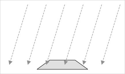
Figure 4
shows the way in which a directional light shines on objects rendered
within a 3D scene. Note that the light has direction but does not have a
position: the rays shown are all parallel and do not converge on any
specific location.
8. How XNA Calculates Light Reflections
The explanations we have
looked at for each light revolve to a significant degree around
determining whether each triangle in a rendered object is facing toward
or away from a light. Triangles that are at the appropriate angle
relative to the light will be illuminated brightly, whereas triangles
facing away from the light will become darker or not be illuminated at
all.
How does XNA tell whether a
triangle is facing toward a light or not? There's nothing magical about
this; in fact, the answer is rather basic: we have to tell XNA the
direction in which each triangle is facing.
We do this just once when we
create our object. When the object is rotating or moving in the game
world, XNA will use this information and apply all the object
transformations to the direction in which the triangle is facing, just
as it does to the position of the vertices. The object lighting will
therefore be automatically and dynamically calculated as each object or
light moves within the scene.
8.1. Describing a Triangle's Face Direction
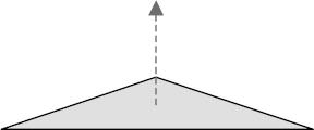
To tell XNA the direction in which each triangle is facing, we provide a Vector3 value known as a normal. A normal describes a line that is pointing in a direction perpendicular to the front of the triangle. Figure 5
shows a single triangle with its normal. The triangle itself is
completely flat with its surface pointing directly upward. The normal,
which is represented by a dashed arrow, therefore points upward, too.
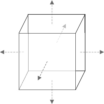
In Figure 6,
a solid shape is shown with its normals. Each side of the cube faces in
a different direction, and once again dashed arrows are used to
indicate the direction of the normal from each side.
To describe each normal, we use a different type of vertex object: VertexPositionNormalTexture. In addition to the Position and TextureCoordinate vectors that we explored already, this object contains an additional vector called Normal.
This vector allows the three different values (for the x, y, and z
axes) to describe the distance along each axis that would need to be
travelled to move along the line of the normal.
For the triangles on top of
the cube whose faces point directly upward, the normal vector would be
(0, 1, 0). This vector shows that to travel along the line of the
normal, we would move zero units along the x and z axes, and 1 unit
along the positive y axis; in other words, we would move directly
upward. The opposite face that points downward would have a normal
vector of (0, - 1, 0). Moving in the direction of this vector would move
us along the negative y axis.
Similarly, the triangles on the
right edge of the cube have a normal vector of (1, 0, 0), and the
triangles at the back of the cube (facing away from us) have a normal
vector of (0, 0, - 1).
We need to provide these
normal vectors to XNA for it to use when our object is being rendered.
We only need to provide the vectors for when the object is in its
default untransformed position. As the object is rotated within the
scene, XNA will recalculate its resulting normal vectors automatically.
Notice that the normals we have
discussed all have a length of 1 unit. This is important because XNA
takes the normal length into account when performing its lighting
calculations, and normal vectors that are longer or shorter than this
might cause the reflected light to become brighter or darker. Vectors
with a length of 1 unit are known as normalized vectors, whereas those with longer or shorter lengths are unnormalized vectors.
Once XNA knows the direction
each triangle is facing, it can work out whether they face toward or
away from the scene's lights and so determine how much light to provide
for the triangle.
8.2. Calculating Normals
Although working out
normal vectors is easy when they are aligned directly along the x, y, or
z axis, they can be much more difficult to work out in your head when
the triangle faces in a direction away from these axes. Calculating the
normals manually for these triangles would be both tedious and prone to
errors.
Fortunately, we are using a
computer (albeit one that fits in your pocket), so we can get it to
calculate the normals for us automatically.
There are all sorts of
mathematical operations that can be calculated on vectors and we can use one
of these called a cross product to calculate the normal for us.
We will now briefly look
at the calculation performed by the cross product, to understand what it
does. Don't worry if you find the arithmetic complex or off-putting,
however, for as you will see in a moment, XNA has support for doing all
this built in to its Vector3 structure,
so we don't have to calculate any of this manually. The explanation here
simply describes what is going on under the covers.
To perform a cross
product calculation, we need to find two vectors that lay along the
surface of our triangle. They are easy to calculate because we can
simply find the difference in position between the vertices of the
triangle. For the purposes of this example, we will call these vectors a
and b.
Consider the triangle shown in Figure 7. It is oriented so that its surface points directly upward (to keep the example simple!) and has vertex coordinates as shown.
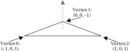
Note that the
triangle vertices are, as always, defined in clockwise order. This is
important to our calculation; if they were defined in counterclockwise
order, the normal we calculate would be facing in the opposite direction
(downward in this case).
To calculate the two
vectors that we need, we subtract the coordinates of vertex 1 from
vertex 2 for the first vector, and subtract the coordinates of vertex 0
from vertex 1 for the second vector, as follows:
Vector a: Vertex 2 – Vertex 1 = (1 – 0, 0 – 0, 1 – −1) = (1, 0, 2)
Vector b: Vertex 1 – Vertex 0 = (0 – −1, 0 – 0, −1 – 1) = (1, 0, −2)
As you can see, these do
indeed represent the distances from each vertex to the next. To move
from vertex 1 to vertex 2, we would need to move 1 unit along the x
axis, 0 units on the y axis, and 2 units on the z axis. To move from
vertex 0 to vertex 1, we would need to move 1 unit on the x axis, 0
units on the y axis and −2 units along the z axis.
To perform the cross
product operation, we need to perform the following calculations on
vectors a and b. These will produce the normal vector n:
n.x = (a.y × b.z) – (a.z × b.y)
n.y = (a.z × b.x) – (a.x × b.z)
n.z = (a.x × b.y) – (a.y × b.x)
Let's substitute in the values for our vectors and see the results:
n.x = (0 × −2) – (2 × 0) = 0 – 0 = 0
n.y = (2 × 1) – (1 × −2) = 2 – −2 = 4
n.z = (1 × 0) – (0 × 1) = 0 – 0 = 0
The resulting vector n is
therefore calculated as (0, 4, 0). This does indeed describe a line in
the positive y axis, directly upward, exactly as we had hoped. The same
calculation can be performed for any triangle regardless of its vertex
locations.
So having seen what the cross
product calculation actually does, let's make things a little simpler
and take a look at how XNA can do this work for us. We still need to
calculate the vectors a and b, but XNA will allow us to simply subtract
one vertex position from another to calculate these. With the a and b
vectors prepared, we can pass them to the static Vector3.Cross function, and it will return the normal. The code required to perform all of this is shown in Listing 1, which uses the same triangle as we used for our manual calculations.
Example 1. Calculating the normal for a triangle
// Create three vertices for our triangle Vector3 vertex0 = new Vector3(-1, 0, 1);
Vector3 vertex1 = new Vector3(0, 0, −1);
Vector3 vertex2 = new Vector3(1, 0, 1);
// Calculate the a and b vectors by subtracting the vertices from one another
Vector3 vectora = vertex2 - vertex1;
Vector3 vectorb = vertex1 - vertex0;
// Calculate the normal as the cross product of the two vectors
Vector3 normal = Vector3.Cross(vectora, vectorb);
// Display the normal to the debug window
System.Diagnostics.Debug.WriteLine(normal.ToString());
|
Hopefully that should be a bit
easier to understand! The output that is displayed by the code is the
vector (0, 4, 0), exactly as with our manual calculations.
The normal vector we have calculated is not normalized, however; its length is 4 rather than 1. XNA's Vector3 structure has a Normalize method that we can call to easily normalize the value however, so we can just let XNA do it for us. The code shown in Listing 2 can be added after the call to Vector3.Cross from Listing 7-14 to normalize the vector.
Example 2. Normalizing the normal vector
The resulting normalized vector is (0, 1, 0)—a unit-length vector pointing directly upward. Perfect.
We will look at
implementing all this in our program code in the section entitled
"Programmatic Calculation of Normals," coming up shortly.
8.3. Surface Normals and Vertex Normals
We have so far considered
normals as applying to each face in our 3D object. In actual fact, it is
not the faces that we apply normals to but the individual vertices that
form the face. It is the vertices for which XNA calculates the color
based on its lighting equations, and it then applies this to the whole
triangle by interpolating the colors between the vertices just as we
have manually interpolated colors ourselves by providing vertex colors.
This gives us an
opportunity to perform a very useful lighting trick. We can provide
different normals for the vertices of a single triangle. XNA will then
consider each vertex of the triangle to be facing in a different
direction and will interpolate the light directions across the surface
of the triangle.
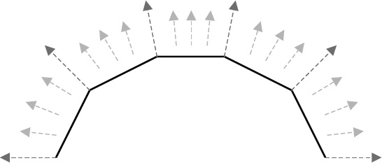
Consider the triangles in Figure 8.
They are shown as thick lines, representing the triangles viewed
edge-on. The long dashed arrows show the normals that have been applied
for each of the vertices within the triangles. Note that for each
triangle, the normals are pointing in different directions (they point
slightly away from one another).
The shorter dashed
arrows show the effective normals within the interior of the triangles
due to interpolation. They smoothly transition from one normal to the
next, giving the impression that the surface of the object when viewed
face on is perfectly smooth, whereas in fact it is created from just
five flat faces.
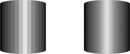
An example of normal interpolation in practice can be seen in Figure 9.
The two images shown are both of the same cylinder, rendered using a
number of flat surfaces. The individual surfaces can be clearly seen in
the image on the left, which uses the same normals for all vertices
within each face. On the right, the vertex normals are modified so that
they differ from one side of the face to the other .
Note that the appearance of this cylinder is entirely smooth, even
though it is formed from the exact same faces as the image on the left.